Apple Lightning Cable
In the last few years the humble charging/connecting cable has been pulled into the spotlight on many occasions. Most recently it’s been the EU’s proposal to force all consumer electronics manufacturers to adopt a standard charging connector, most likely USB-C. Despite being a fairly mundane accessory, it seems these cables receive a fair bit of attention.
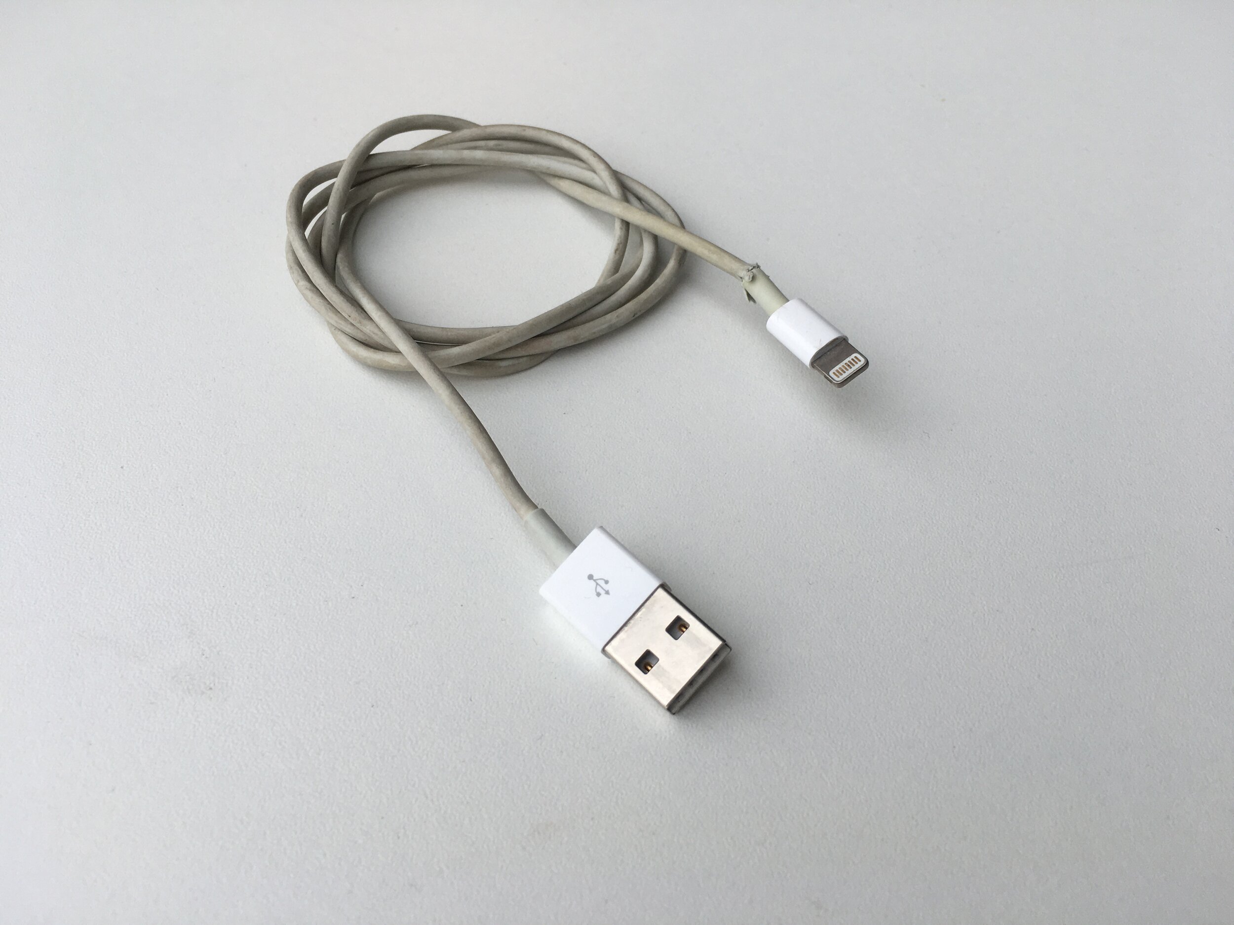
In the spirit of this news, I decided to teardown the USB-A/Lightning cable that came with my iPhone 6S (purchased Fall 2015) to see what went into making it..
Cable Fray:
First, I feel like I need to address the obvious point of wear present on this charging cable. After several years of use, the lightning connector side of the cable is showing considerable fraying. A quick google search shows that this problems seems to occur most often on the lightning connector side of the cable - but why does this fray occur in the first place and how can it be prevented?
Nearly all cables are designed with a strain reliever which stiffens the area immediately after where the cable is soldered to the connector. This prevents extreme bending of the cable from directly putting stress the brittle soldering points on the connector. While this design stops the solders from being stressed, extreme bend angles will now occur between the strain reliever and the cable and will instead stress the cable sheath.
I’ve certainly plugged my phone in to charge and then wrapped the excess cable around the phone, or balanced my phone in a cupholder directly on its connector, or even just used my phone while the charging cable was bent at an extreme angle to reach an outlet. All of these situations are not outside of normal every day use, yet the cable angles are produced can cause damage to the cable overtime.
There are several solutions to this problem - braided cable sheaths, longer/more compliant strain relief features - but Apple didn’t choose to use these designs on their build. Several factors could have dictated this decision and most are quick to jump to aesthetics as the main factor, which could certainly be it, however it’s also possible that a more robust strain reliever would limit the mobility of the cable and prevent or inhibit many of the behaviours that I consider part of normal every day use.
Additionally, a stiffer/longer strain reliever will increase the moment arm through which force is transferred. This subsequently increases the force on the small metal connector inserted inside of the phone, making it easier to accidentally torque the connector and damage the internals of the phone.
Material:
An additional note on cable fray. Most charging cables on the market use a durable PVC material for their sheath. This material has some significant negative environmental/health impacts due to the addition of a phthalate (pr. THAL-ates) plasticizer used to soften the PVC. Apple removed the use of PVC from all of their products, which is commendable, however PVC is well known for its durability. This material change could also be a factor contributing to the durability of their cable sheaths.
With that lengthy bit of chat about cable fray over, let’s take this cable apart!
I start with the lightning connector side of the cable. Since these cables are not meant to be disassembled, this teardown requires a full destructive disassembly.
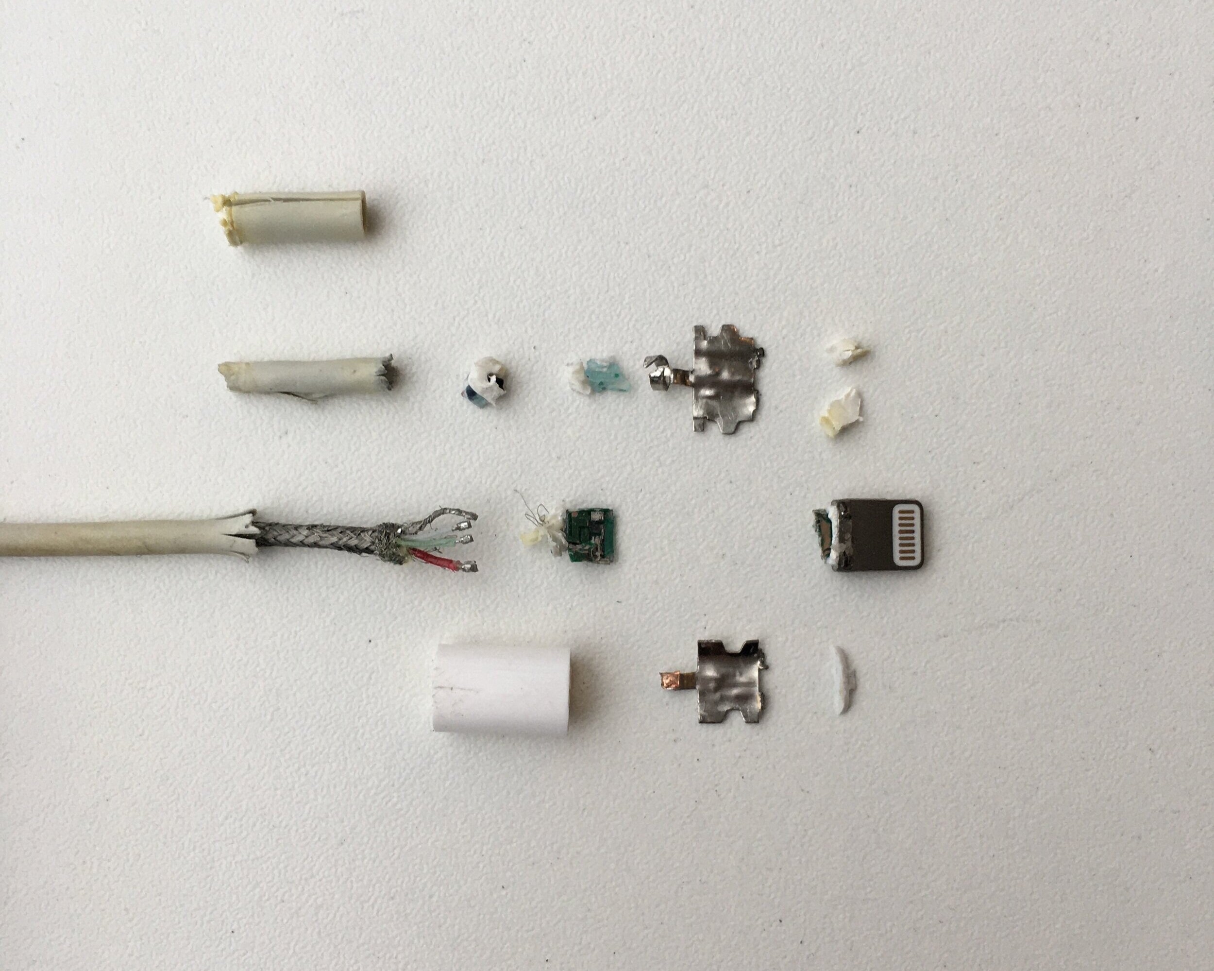
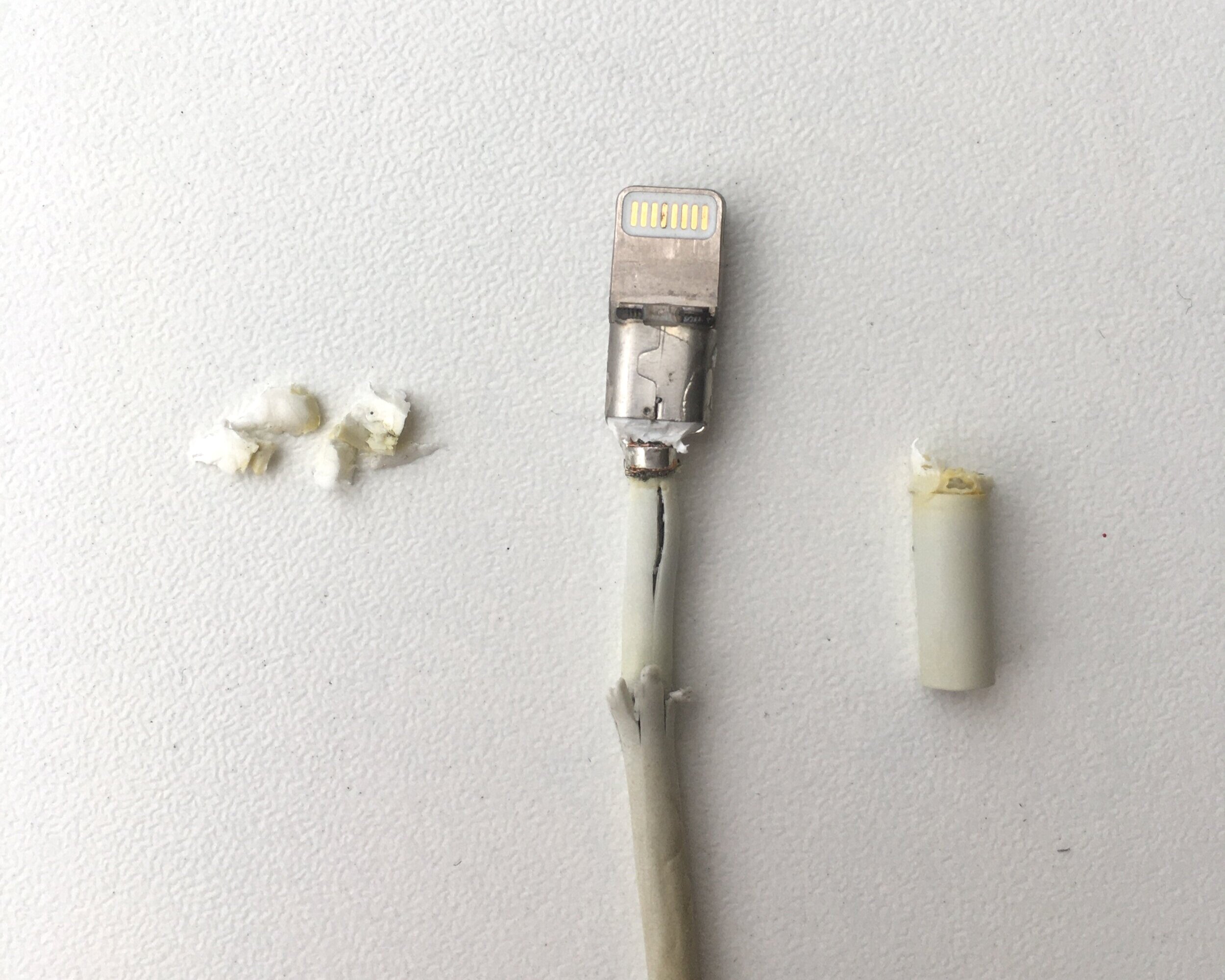
I first cut off the polycarbonate plastic outer which has been molded onto the cable during one of the final stages of manufacturing.
With the outer cover removed I’m able to pick off two tiny injection molded parts, which were fit onto the connector end. These two components are visible on the finished product and cap the open end of the hard plastic cover.
Next I cut away some soft material which feels like it could be silicone from the base of the cable shield. This material is used to provide support to the soldered wired by filling the shield with a semi-rigid material, making the connector more robust while also sealing the electronics from water ingress.
I also cut away the strain reliever from the connector cable. It’s important to note that the strain reliever is an independent from the actual cable’s sheath, however it does seem to be adhered to the sheath. The strain reliever is also slightly thicker, coming in at 0.65mm whereas the cable sheath is 0.40mm.
The strain reliever serves to stiffen the cable and reduce the extreme bends which can occur directly at the connector, moving it further away from the soldered connectors. Normally these features aim to create a smooth bend radius in the cable as opposed to an abrupt bend, however the Apple cable relievers seem to be a bit too stiff to allow this to happen.
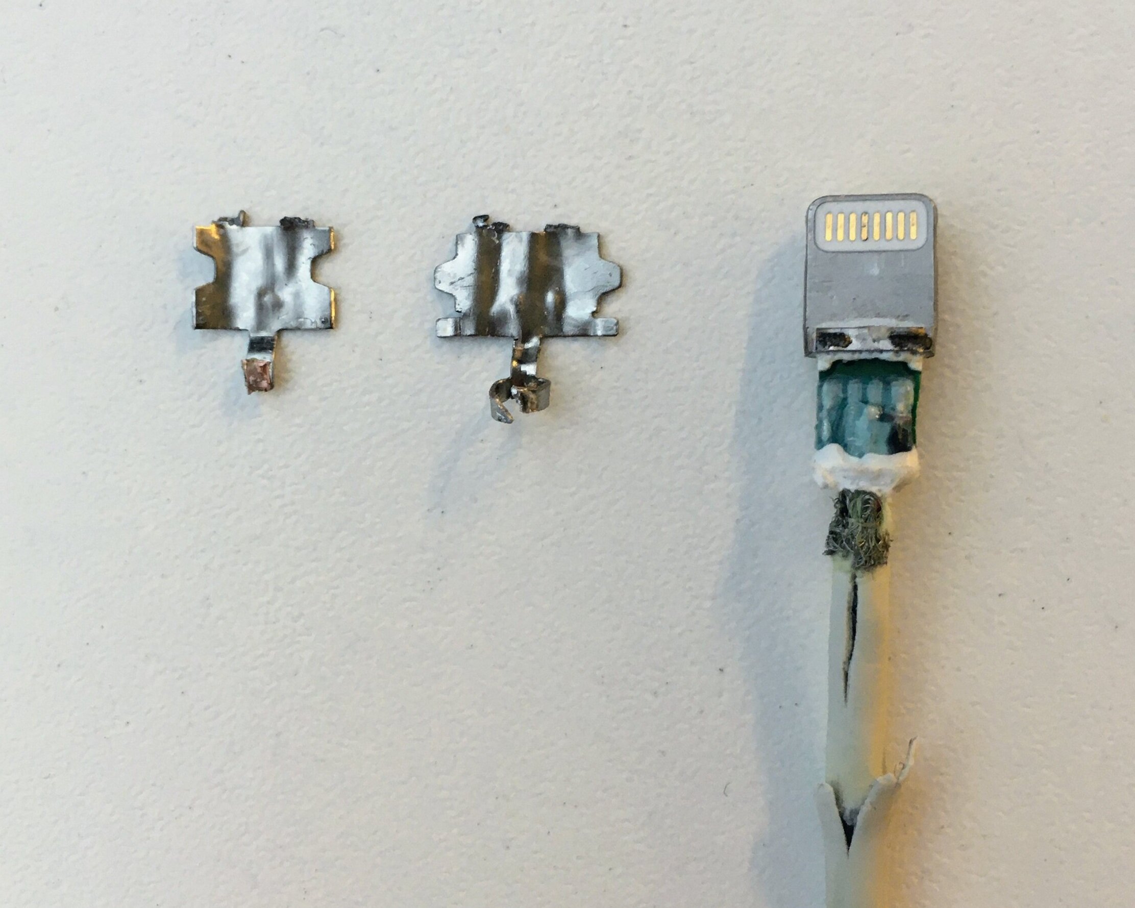
Next I set my sights on removing the shield covering the connector chip. The shield has trapezoidal interlocks on it as well as a tiny spot weld on each side which keeps the two halves together. These were very difficult to get off without a Dremel, but I eventually managed after plenty of squishing and twisting.
With the metal shielding removed I find a small board covered in a soft, transparent material. This potting protects the board from shock/vibration, water ingress, and potentially also the heat from the subsequent injection molding steps.
While this cable is official from Apple. There are non-Apple cables sold by third party companies that do get an Apple certification. Basically, if a company wants to produce an official Apple certified lightning cable, they need to buy the entire connector end with the board installed, then they are responsible for soldering the leads on and providing a cover. When this is done, the company can brand the cable as MFi (made for iProducts).
The important bits of the proprietary connector are the chips themselves. When the connector is inserted, the board shakes hand with the device and communications information about what data is being transmitted. Another chip on the board monitors and regulates the voltage going into the device and is able to manage any fluctuations to avoid damaging internals.
At this point the lightning connector is fully torn down. I broke the board in half trying to pull it from the metallic connector head, however the board seems to have been molded with the plastic directly into the lightning connector head. It’s a shame that the cable does begin to fray over time, because the build quality on the rest of the connector is extremely high.
I decided I wanted to take a look at the metallic part which contained the lightning board and gold contacts, which involved getting more destructive. I burned the plastic out of the connector and was able to free the board and contacts from it. After cleaning off the char and soot, I get a closer look at the lightning connector itself.
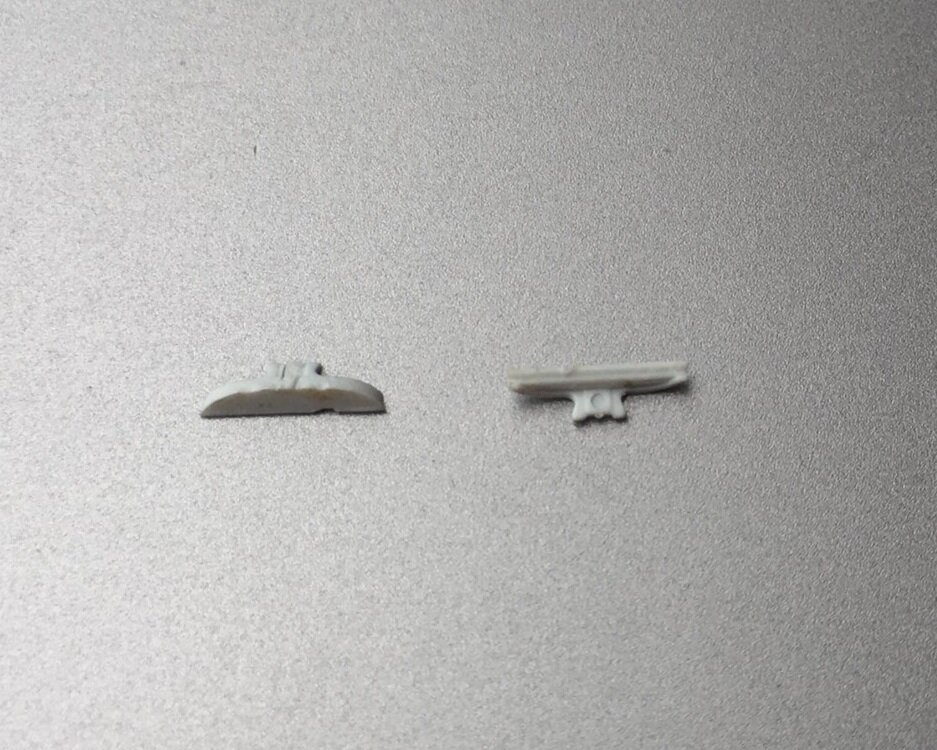
This part is tiny and features some really intricate details. The part is a magnetic steel and is likely made by metal injection molding. When taking a really close look at it, I noticed there seems to be some marking on the inside of the connector.
I can just make out two small markings, one on either side of the connector. These are incredibly small, with the lettering being maybe .3 mm high. It can be hard to see from the images below, but image left reads “E77 F” and image right reads “60 6”.
I’m not 100% certain on their meaning. My initial thought was that they were material grade markings, the 60 6 maybe being some kind of nylon and E77 F being some MIM alloy I’m not familiar with, but they could also refer to the chips being used on the PCB. One of the chips on this board is the “E75” chip and this lightning connector has gone through several evolutions, perhaps this model uses an iteration of the E75 chip called E77? This could also be a marking that indicates which particular mold made the part similar to the information normally stamped on injection molded parts. All of these are more or less guesses, but it was an interesting find!
USB-A Side:
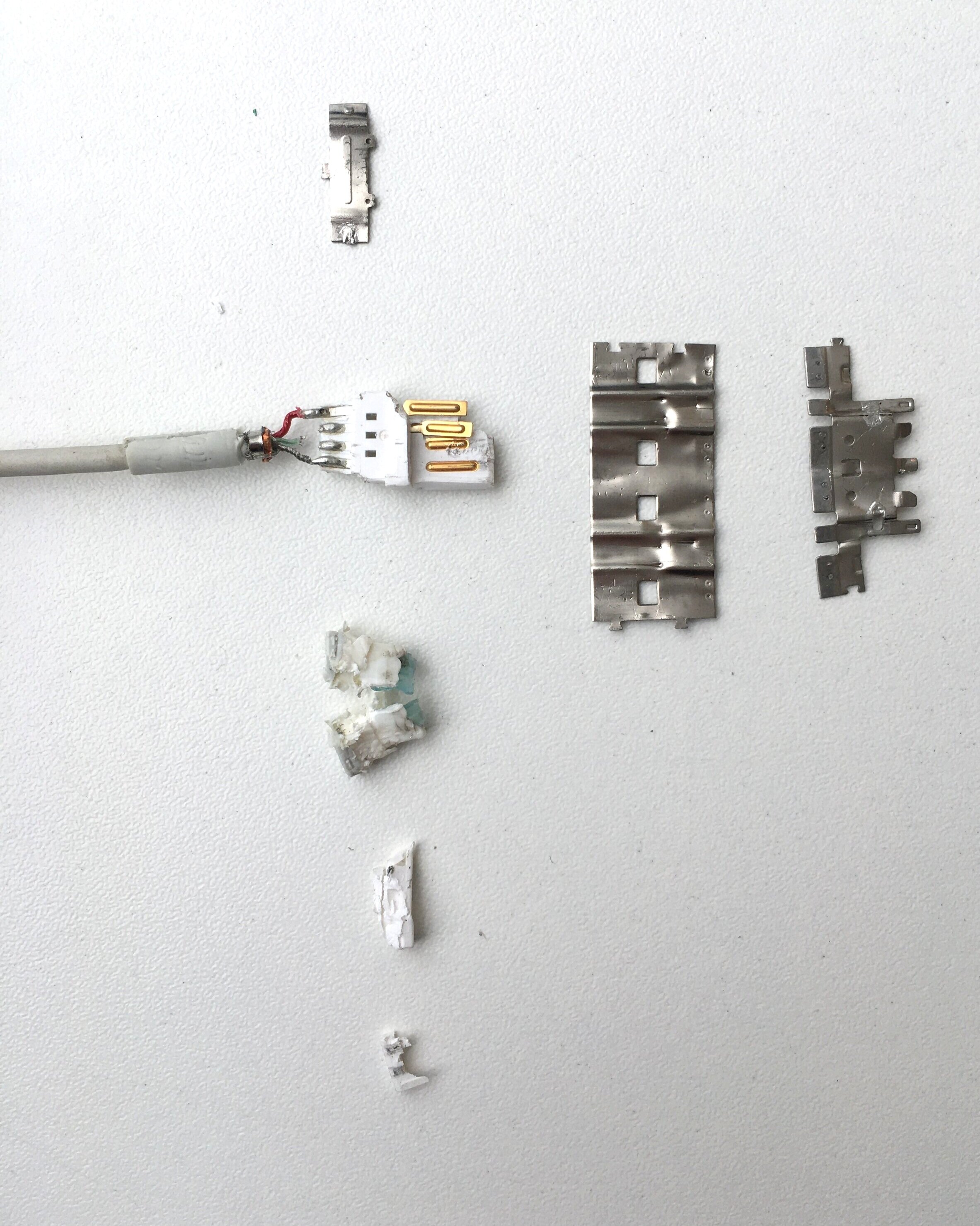
Now onto the USB-A side of the connector. I first cut away the polycarbonate shell to find some interlocking sheet metal parts, similar to those on the lighting connector. I cut off a semi-rigid plastic from the base of the connector which is used to support the wires soldered onto the USB terminals.
Unfortunately, the brackets were much more difficult to separate than on the USB-C connector and took quite a bit of squishing and prying before they would release.
Eventually, I managed to separate the shielding brackets which are actually comprised of three individual sheet metal parts. Each part is folded four times and spot welded onto itself before nesting into the other metal shields and receiving an additional weld. The smallest of the three brackets wraps around the cable sheath, securing the shielding to the cable.
The shielding covers a hard plastic part with four gold plated terminals molded into it. These terminals are insert molded into the white plastic before being soldered to the four wires. With the shielding removed from the plastic terminal, the USB connector is fully disassembled.
With that the cable is fully torn down!
